

Recently, I’ve been playing with some old hardware: transputer Farmcards made by Perihelion in about 1988. Happily they still work perfectly, but I found the online documentation to be wrong about the boards’ diagnostic bus.
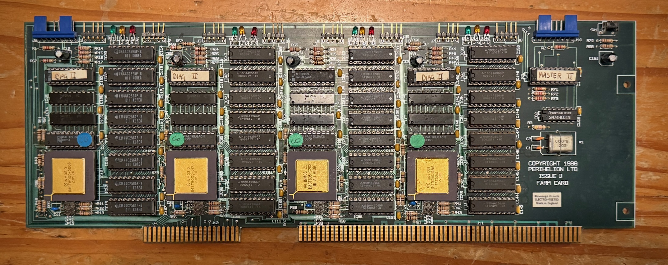
A technical manual1 for the Farmcard can be found in the usual transputer archives e.g. Geekdot2.
Overview
The Farmcard was Perihelion’s standard transputer module. It contains four T800s, each with 1MB of RAM. The transputers are connected in a square, with eight external links:
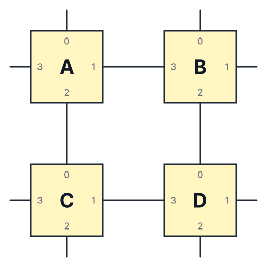
These links are brought to both 0.1" headers and to the edge of the PCB so that the card can be plugged into a backplane and everything just works.
All of this works just like it says in the manual.
Diagnostics
Besides the transputer links, the Farmcard has a diagnostic bus which allows individual transputers to be reset or analysed. The host drives three signal lines, and transputers can assert a common error signal which the host reads. Decoding the signals is accomplished by PALs, and sadly I don’t have their programming details.
The Farmcard manual describes a complicated protocol which does not match how my Farmcards work. The manual calls the control signals Fast, Slow and L, but it’s hard to give those words sensible meanings.
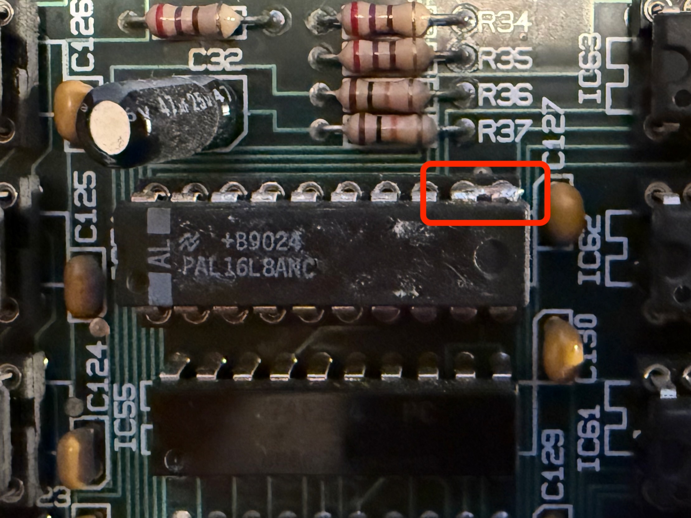
I wonder if my cards are unusual in some sense: they are issue D cards, but the PALs have been bodged by shorting pins 9 and 10. So, whilst I am confident that this is how my cards work I don’t know if it’s true for other cards.
Given three control lines, I wondered what I’d do. After some thought it seemed to me that all you really needed was a long shift-register: two lines to clock in the data and one to copy it to the outside world. Happily this seems to be the case!
Explicitly:
Each transputer gets two bits of the shift-register. The last two bits clocked-in control the transputer nearest to the host.
Reset is shifted in first, then analyse.
L is used for data, Fast for clock, and Slow to latch the data.
We need to know how many transputers are connected to the bus so that we always clock enough bits to clear out any old state. Clocking too many bits just wastes time; clocking too few actually causes errors.
Here’s a micropython program suitable for driving the diagnostic bus from something like a Pi Pico:
from machine import Pin
from time import sleep_us, sleep_ms

p_s = Pin(26, Pin.OUT)
p_f = Pin(22, Pin.OUT)
p_l = Pin(20, Pin.OUT)

max_nodes = 32

def init():
    p_s.value(0)
    p_f.value(0)

def set_all(r, a):
    for i in range(max_nodes):
        p_l.value(r)
        sleep_us(1)

        p_f.value(1)
        sleep_us(1)
        p_f.value(0)
        sleep_us(1)

        p_l.value(a)
        sleep_us(1)

        p_f.value(1)
        sleep_us(1)
        p_f.value(0)
        sleep_us(1)

def update():
    p_s.value(1)
    sleep_us(1)
    p_s.value(0)
    sleep_us(1)

init()

while True:
    set_all(1,0)
    update()

    sleep_ms(1000)

    set_all(0,0)
    update()

    sleep_ms(500)
It pulses the reset lines on all the transputers, so you should see the red LEDs on the Farmcard flashing.
Hardware setup
We need to connect three Pico outputs to the diagnostic bus:
| Signal | GPIO | Diagnostic pin |
|---|---|---|
| L | 20 | 1 |
| Fast | 22 | 3 |
| Slow | 26 | 5 |
| GND | - | 2,9 |
One could also connect the Error signal to a Pico input, but I didn’t bother.
There’s also a Global Reset input on the diagnostic bus, which is marked as active low in the manual. It didn’t seem to do anything though, so I just tied it high.
The PALs expect 5V logic levels. I used a 74LS125 buffer as a level-shifter, and it seemed to work reliably.
New hardware
Although the implementation with PALs seems rather quaint today, the basic control scheme still seems sound.
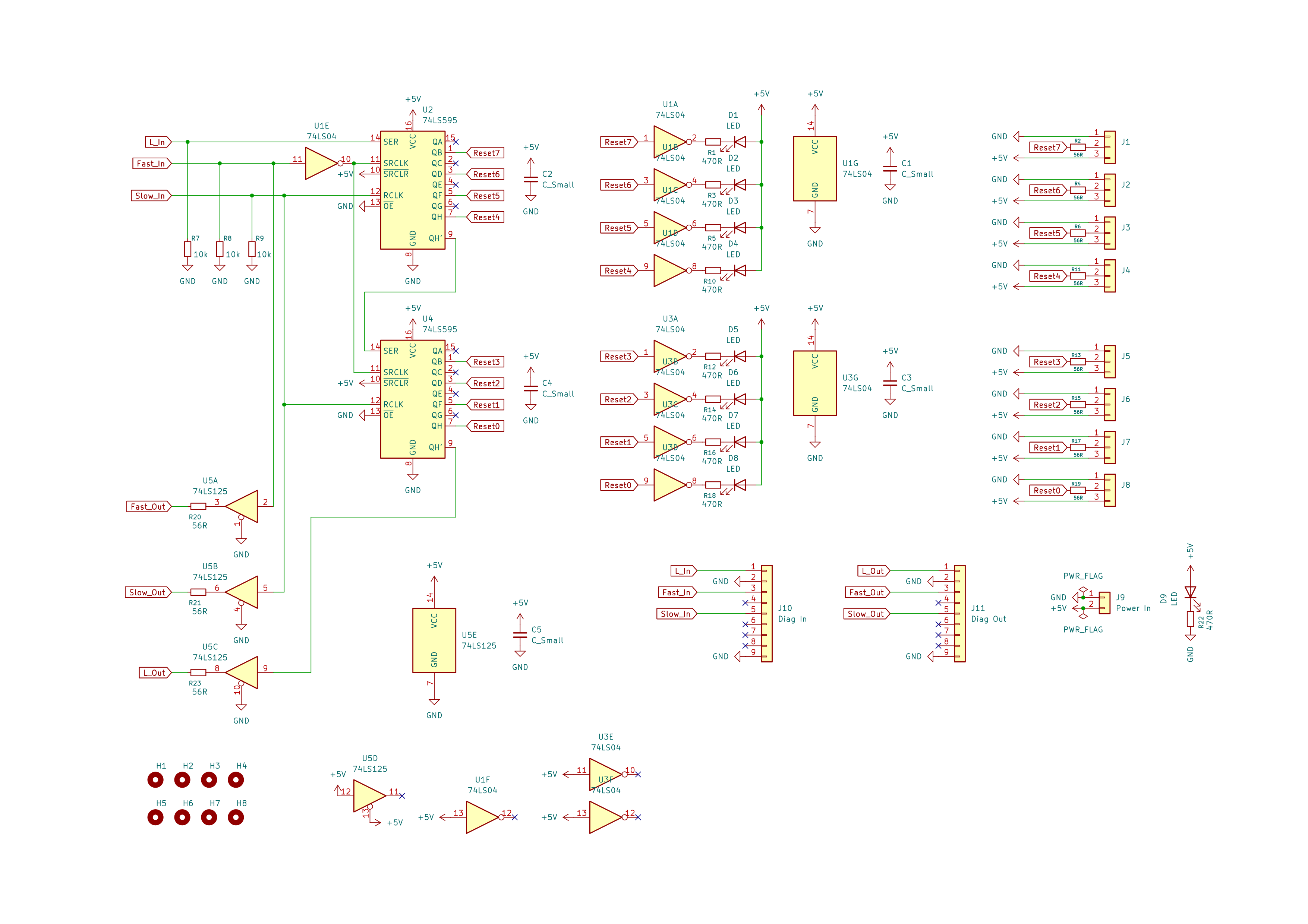
So if you want to add transputers not on a Farmcard to a Diagnostic bus, here’s the schematic for a control board for eight devices using 74 series logic.
 3
The 595 triggers in the opposite sense to the PALs. I didn’t check whether the PALs are edge or level triggered, but without the inverter if the 595s drive the Farmcard a bit gets lost.
I don’t care about Analyse so the outputs corresponding to those bits in the shift register aren’t routed.
Miscellanea
There’s a school of thought which says you should replace old electrolytic capacitors, so I did that before powering up the Farmcard.
References
- 1. Farmcard_Manual.pdf
- 2. https://www.geekdot.com/uploads/files/transputer/Farmcard_Manual.pdf
- 3. tsb-schematic.pdf
