

This article is part of a series documenting my first foray into FPGA programming. You might find it helpful to read the summary article1 first.
Introduction
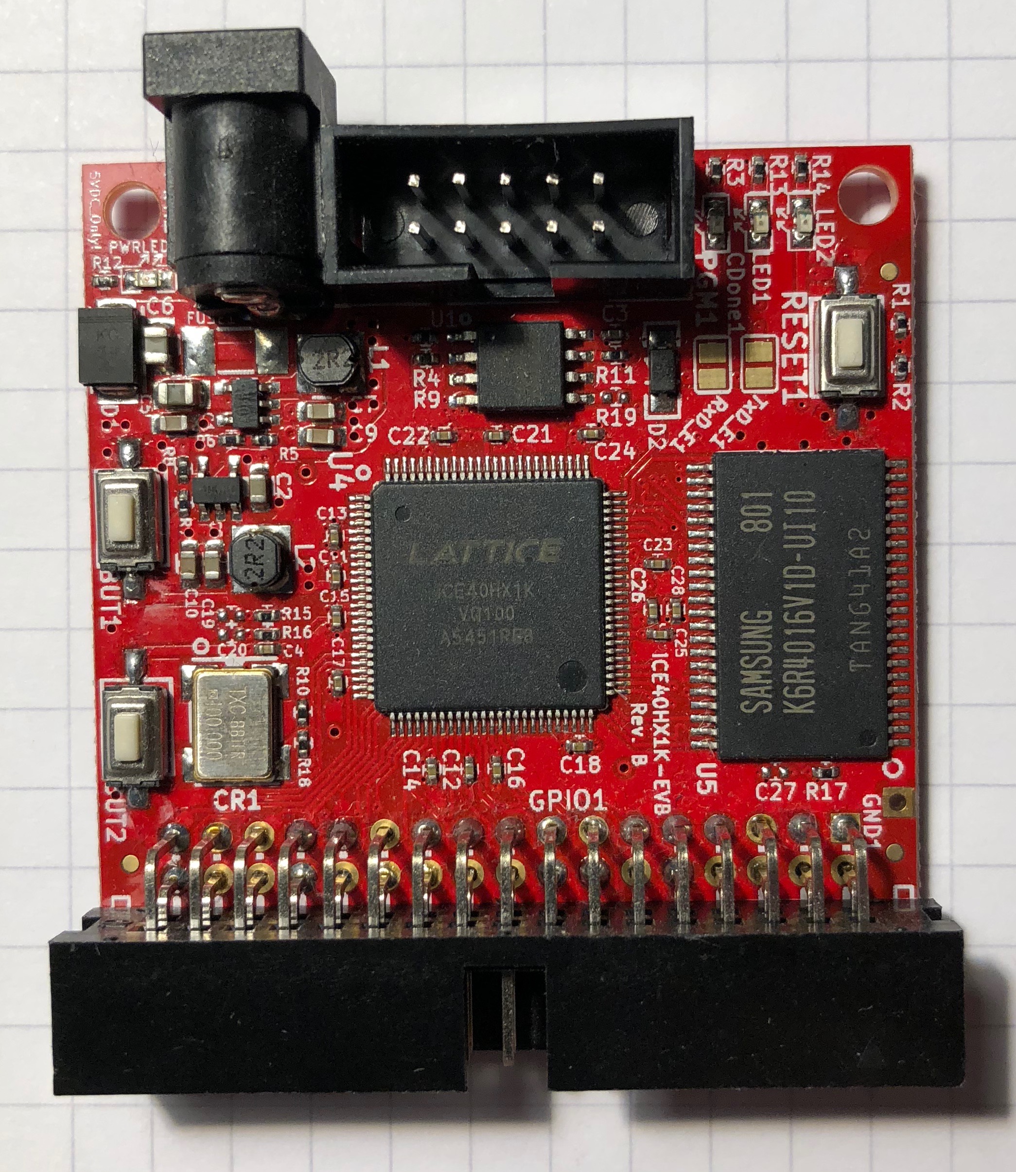
Olimex make a development board for the HX1K2. The board’s design is entirely open: it’s on GitHub3.
Unlike the boards from Lattice, it does not contain a programmer: rather Olimex suggest using one of their Arduino clones to do the task. There’s also no USB connection for a computer: it seems much more a standalone product.
Walkthrough
Two steps are common to all the boards:
- Install the iCE40 toolchain4.
- Clone the repo:
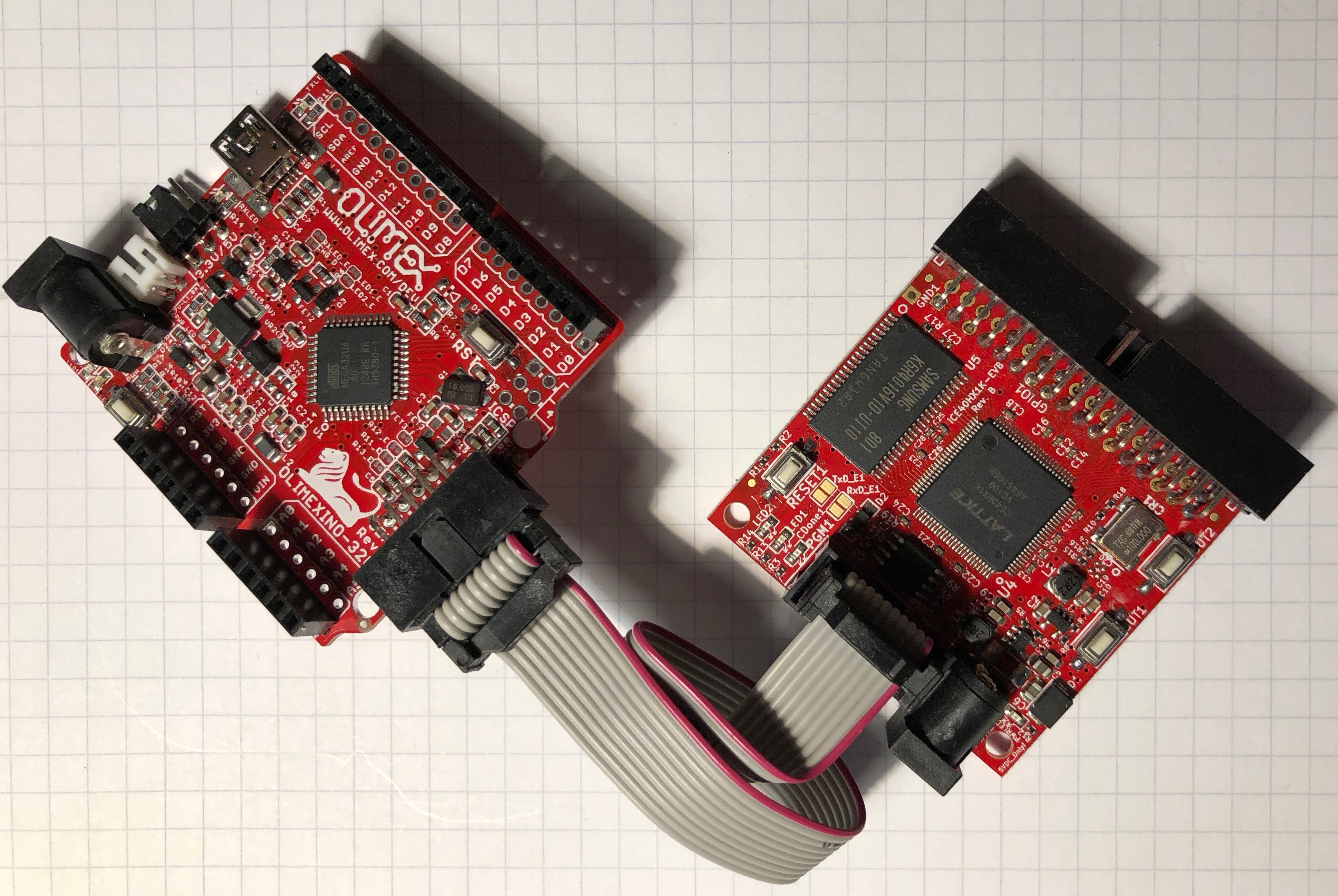
$ git clone https://github.com/mjoldfield/ice40-blinky.gitNext you will need to acquire an FPGA programmer. Olimex suggest programming an Arduino: this is documented below5. Having configured the Arduino, connect it to the FPGA board:
Now we must attend to the power. There isn’t a USB port on this board, so you can”t directly power it from a computer. Instead you have to choose between:
- connecting a 5V DC supply to the jack socket on the board;
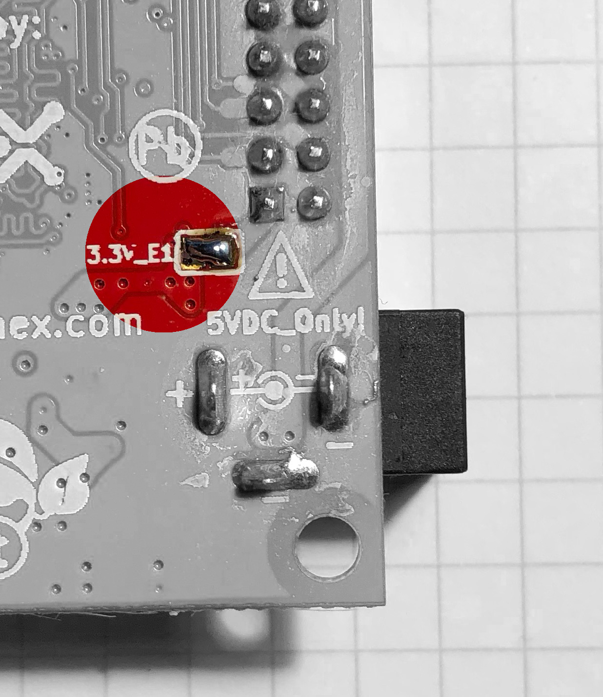
- supplying power to the 3.3V pin on the programming header.
The latter is most convenient, but you need to bridge an open solder-bridge on the bottom of the PCB to enable it.
Now you can build the relevant demo, and flash it to the board:
$ cd olimex-hx1k/
$ make flash
Finally, enjoy the blinkenlights6!
Testing
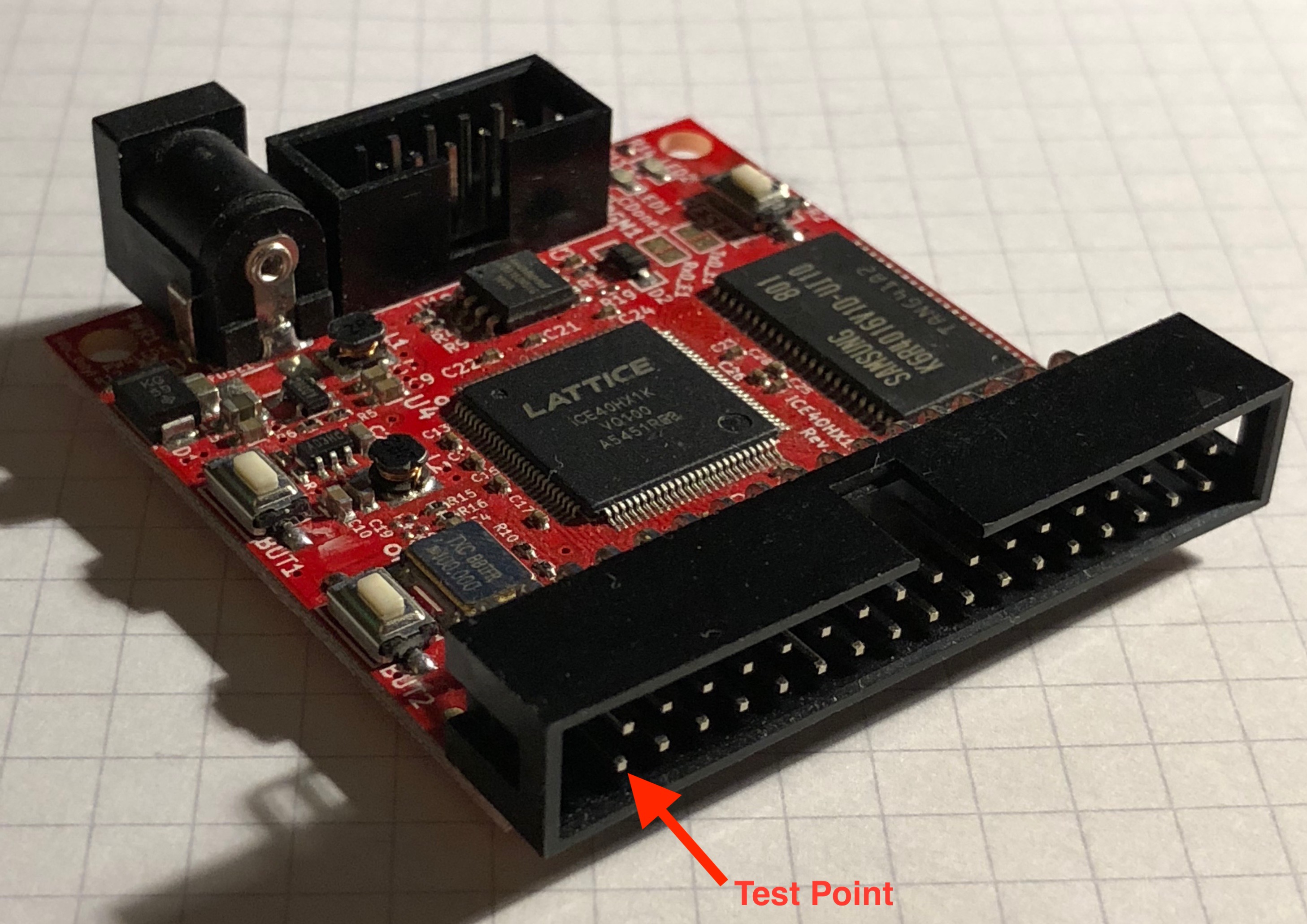
If you have a frequency counter to hand, measure the frequency on pin 34 of the IDC connector. You should see a 6.25MHz square wave.
Hardware Notes
The board’s design is entirely open: it’s on GitHub7.
FPGA
The FPGA is a iCE40HX-1K in a 100-pin flatpack.
Clock and PLL
A 100MHz oscillator module drives pin 15.
In this package the HX1K has no PLL.
LEDs
Two red LEDs are provided on pins 40 and 51.
Test point
As befits the name breakout board, many spare IO pins exist, and we use pin 24 as a test point.
Software Notes
Please remember that you can download all of this from GitHub8.
There are only three files: the verilog, the pin definitions, and a Makefile.
The main source code
The code is very simple: there are just two LEDs and they flash at 1Hz.
/*
 * Top module for Olimex iCE40HX1K-EVB blinky
 *
 * Bounce LEDs
 *
 * Generate test signal: 6.25MHz
 */

module top(input CLK
       , output LED1
       , output LED2
       , output TSTA
       );

   // No PLL, so use 100MHz external clock
   wire sysclk;
   assign sysclk = CLK;

   // We want to do a 2-cycle pattern in 1s, i.e. tick at
   // 2Hz. log_2 (100M / 2) = 25.6. so use a 26-bit counter
   localparam ANIM_PERIOD    = 100000000 / 2;
   localparam SYS_CNTR_WIDTH = 26;

   reg [SYS_CNTR_WIDTH-1:0] syscounter;
   reg                 led_strobe;

   always @(posedge sysclk)
     if (syscounter < ANIM_PERIOD-1)
       begin
      syscounter <= syscounter + 1;
      led_strobe <= 0;
       end
     else
       begin
      syscounter <= 0;
      led_strobe <= 1;
       end

   reg             ledState;
   always @(posedge sysclk)
     if (led_strobe)
       ledState <= !ledState;

   assign LED1 =  ledState;
   assign LED2 = !ledState;

   // test signal: 100MHz / 2^4 = 6.25MHz
   assign TSTA = syscounter[3];

endmodule
Makefile
Most of the rules are shared across different dev. boards: we need only to specify the FPGA and the programming software:
ARACHNE_DEVICE = 1k
PACKAGE      = vq100

ICETIME_DEVICE   = hx1k

PROG_DEV     = $(wildcard /dev/cu.usbmodem*)
PROG_BIN     = iceprogduino -I$(PROG_DEV)

include ../std.mk
Pin summary
Finally, we need to tell the software which pins are associated with the signals:
$ cat pins.pcf
set_io LED1 40
set_io LED2 51
set_io CLK  15
set_io TSTA 24
The Arduino FPGA programmer
Olimex recommend using their Olimexino-32U49 board for this. I think it’s roughly the same as an Arduino Leonardo, but it comes with a UEXT header which has precisely the right pin out for the programming header on the Olimex FPGA board.
If you try to use a different Arduino, make sure it uses 3.3V signals, rather than 5V.
The sketch for the board is in the FPGA board’s GitHub repo10, but you also need a particular SPIFlash library. More explicit details can be found on the Olimex website11.
Having flashed the hardware, we now need to install software on the Mac to drive it. That too is from GitHub12:
$ make
$ make install
On the Mac, the Arduino appears as a usbmodem device in /dev:
$ ls /dev/*usbmodem*
/dev/cu.usbmodem14431  /dev/tty.usbmodem14431
Of these, you need the cu.usbmodem version. The number in the device name reflects its place on the USB buses, and so changes if you plug it in to a different socket. If you just have one such device though, you can use a wildcard, and program the FPGA thus:
$ iceprogduino -I/dev/cu.usbmodem* foo.bin References
- 1. http://ice40-blinky.html
- 2. https://www.olimex.com/Products/FPGA/iCE40/iCE40HX1K-EVB/open-source-hardware
- 3. https://github.com/OLIMEX/iCE40HX1K-EVB
- 4. ./ice40-toolchain.html
- 5. #ard_prog
- 6. https://en.wikipedia.org/wiki/Blinkenlights
- 7. https://github.com/OLIMEX/iCE40HX1K-EVB
- 8. https://github.com/mjoldfield/ice40-blinky
- 9. https://www.olimex.com/Products/Duino/AVR/OLIMEXINO-32U4/open-source-hardware
- 10. https://github.com/OLIMEX/iCE40HX1K-EVB/tree/master/programmer/olimexino-32u4%20firmware
- 11. https://www.olimex.com/wiki/ICE40HX1K-EVB#Preparing_OLIMEXINO-32U4_as_programmer
- 12. https://github.com/OLIMEX/iCE40HX1K-EVB/tree/master/programmer/iceprogduino
![[ Atom Feed ]](../../atom.png "Atom Feed")