

Introduction
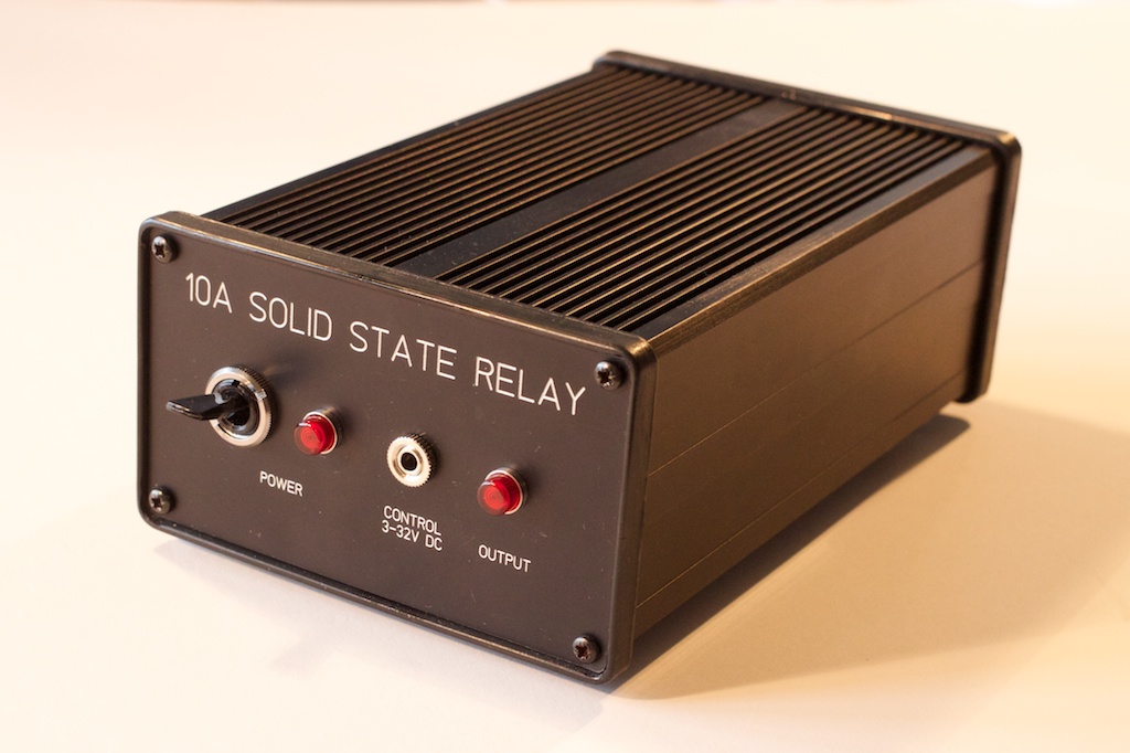
I wanted to control an oven from a microcontroller, which inevitably means switching reasonably high-power mains electricity. The scope for lethal mistakes here seems all too real, and worrying about those is a fine way to get nothing done. Reductionism seemed a good antidote, so I built a box with a solid-state relay in it, tested and debugged it before worrying about the oven. Unsurprisingly, it turned out to be quite easy!
Crude specifications
The main thing to decide is how much current the box should handle. The oven I wanted to control is rated at 1.4kW or about 6A. IEC mains sockets are good for 10A, so I chose that.
Bill of materials
SSR
In a fairly unscientific way, I ended up looking at the Crydom Series 1 SSRs.1 I wasn’t sure that the 10A model would suffice without an enormous heatsink, the 25A model was out of stock at Farnell, so I ended up with the 50A rated D2450PG.2
This SSR accepts a control voltage of 3–32V and will tolerate a reverse polarity input in this range. So I just wired the input of the SSR straight to the front panel. Low-voltage logic will need a boost to drive it, but such is life.
Assuming the worst-case voltage drop of 1.15V across the relay whilst delivering 10A leads to 11.5W of power being dissipated. The 50A model has a thermal resistance between the junction and case of 0.45°C/W, so we’d expect the junction to be less than about 5°C above the SSR case.
The SSR was mounted on a HSP-1 thermal pad.3
Case
Somewhat inevitably the case came from Hammond:4 a natty black anodized-aluminium affair with heatsink-like ridges. Case 4316215 is wide enough to bolt the SSR to the base.
I ordered front and back panels from Schaeffer AG.6 You’re welcome to the design files,7 but note:
- The corner radius is too small: you can either make it larger or just slightly trim the plastic end plates.
- It’s probably sensible to use an isolated connector for the DC control voltage. This didn’t occur to me until I’d got the panels and I ended up using the two signal lines in a 3.5mm stereo jack plug. You could probably do better.
IEC connectors
The case cutouts match connectors from Schurter:
Front panel
None of this is critical:
- A 20A SPST toggle switch, 12.7mm cutout, e.g. C1700HOAAC from Arcolectric10
- Two 250V neons, 6.4mm cutout, e.g. IND515205-240-T/RD from CamdenBoss11
- Control socket, 6.3mm cutout.
In operation
Heating
I’ve not tried the relay at 10A, but I powered the 1.4kW over for about twenty minutes quite happily. Indeed I could couldn’t discern any appreciable heating by feeling the bottom.
Zero-crossing
To reduce noise, the SSR only switches when there’s no current flowing i.e. at the AC’s next zero-crossing. This implies that it would make a lousy dimmer switch, but for the oven it’s fine.
The plot below shows the current flow during switching (measured in a very crude and noisy fashion) through a light-bulb when the SSR was driven with a 1Hz, 80% duty signal. Red points correspond to the time when the control signal was off; green to on.


Notice that the SSR only turns the current on or off at the first zero-crossing after the control signal has changed state.
References
- 1. http://www.crydom.com/en/Products/Catalog/s_1.pdf
- 2. http://uk.farnell.com/jsp/search/productdetail.jsp?SKU=1200245
- 3. http://www.crydom.com/en/Products/Catalog/h_sp_1.pdf
- 4. http://www.hammondmfg.com/sinkbox.htm
- 5. http://www.hammondmfg.com/pdf/531621.pdf
- 6. http://www.schaeffer-ag.de/en/
- 7. http://mjoldfield.com/atelier/2014/04/ssr/panels.tar.gz
- 8. http://www.schurter.co.uk/var/schurter/storage/ilcatalogue/files/document/datasheet/en/pdf/typ_6200.pdf
- 9. http://www.schurter.co.uk/var/schurter/storage/ilcatalogue/files/document/datasheet/en/pdf/typ_6600-4.pdf
- 10. http://www.arcolectric.co.uk/PDFS/catalogue/Pages/P036-037|LeverSwitches_171.pdf
- 11. http://www.camdenboss.com/indicators/neon/6-4mm-cutout/6-4mm-cutout-threaded-240v-stripped-wire
![[ Atom Feed ]](../../atom.png "Atom Feed")